| Paradigm | Procedural, Imperative |
|---|---|
| Designed by | Massachusetts Institute of Technology |
| First appeared | 1950s (first edition) |
| Filename extensions | .gcode, .mpt, .mpf, .nc and several others |
| Major implementations | |
| many, mainly Siemens Sinumerik, FANUC, Haas, Heidenhain, Mazak. Generally there is one international standard—ISO 6983. | |
G-code (also RS-274) is the most widely used computer numerical control (CNC) programming language. It is used mainly in computer-aided manufacturing to control automated machine tools, and has many variants.
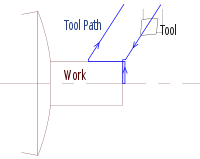
G-code instructions are provided to a machine controller (industrial computer) that tells the motors where to move, how fast to move, and what path to follow. The two most common situations are that, within a machine tool such as a lathe or mill, a cutting tool is moved according to these instructions through a toolpath cutting away material to leave only the finished workpiece and/or, an unfinished workpiece is precisely positioned in any of up to nine axes[1] around the three dimensions relative to a toolpath and, either or both can move relative to each other. The same concept also extends to noncutting tools such as forming or burnishing tools, photoplotting, additive methods such as 3D printing, and measuring instruments.
The first implementation of a numerical control programming language was developed at the MIT Servomechanisms Laboratory in the late 1950s. In the decades since, many implementations have been developed by many (commercial and noncommercial) organizations. G-code has often been used in these implementations. The main standardized version used in the United States was settled by the Electronic Industries Alliance in the early 1960s.[citation needed] A final revision was approved in February 1980 as RS-274-D.[2] In other countries, the standard ISO 6983 is often used, but many European countries use other standards. For example, DIN 66025 is used in Germany, and PN-73M-55256 and PN-93/M-55251 were formerly used in Poland.
Extensions and variations have been added independently by control manufacturers and machine tool manufacturers, and operators of a specific controller must be aware of differences of each manufacturer's product.
One standardized version of G-code, known as BCL (Binary Cutter Language), is used only on very few machines. Developed at MIT, BCL was developed to control CNC machines in terms of straight lines and arcs.[3]
During the 1970s through 1990s, many CNC machine tool builders attempted to overcome compatibility difficulties by standardizing on machine tool controllers built by Fanuc. Siemens was another market dominator in CNC controls, especially in Europe. In the 2010s, controller differences and incompatibility are not as troublesome because machining operations are usually developed with CAD/CAM applications that can output the appropriate G-code for a specific machine through a software tool called a post-processor (sometimes shortened to just a "post").
Some CNC machines use "conversational" programming, which is a wizard-like programming mode that either hides G-code or completely bypasses the use of G-code. Some popular examples are Okuma's Advanced One Touch (AOT), Southwestern Industries' ProtoTRAK, Mazak's Mazatrol, Hurco's Ultimax and Winmax, Haas' Intuitive Programming System (IPS), and Mori Seiki's CAPS conversational software.
G-code began as a limited language that lacked constructs such as loops, conditional operators, and programmer-declared variables with natural-word-including names (or the expressions in which to use them). It was unable to encode logic, but was just a way to "connect the dots" where the programmer figured out many of the dots' locations longhand. The latest implementations of G-code include macro language capabilities somewhat closer to a high-level programming language. Additionally, all primary manufacturers (e.g., Fanuc, Siemens, Heidenhain) provide access to PLC data, such as axis positioning data and tool data,[4] via variables used by NC programs. These constructs make it easier to develop automation applications.
G-codes, also called preparatory codes, are any word in a CNC program that begins with the letter G. Generally it is a code telling the machine tool what type of action to perform, such as:
There are other codes; the type codes can be thought of like registers in a computer.
It has been pointed out over the years that the term "G-code" is imprecise because "G" is only one of many letter addresses in the complete language. It comes from the literal sense of the term, referring to one letter address and to the specific codes that can be formed with it (for example, G00, G01, G28), but every letter of the English alphabet is used somewhere in the language. Nevertheless, "G-code" is metonymically established as the common name of the language.
Some letter addresses are used only in milling or only in turning; most are used in both. Bold below are the letters seen most frequently throughout a program.
Sources: Smid 2008;[5] Smid 2010;[6] Green et al. 1996.[7]
| Variable | Description | Corollary info |
|---|---|---|
| A | Absolute or incremental position of A axis (rotational axis around X axis) | Positive rotation is defined as a counterclockwise rotation looking from X positive towards X negative. |
| B | Absolute or incremental position of B axis (rotational axis around Y axis) | |
| C | Absolute or incremental position of C axis (rotational axis around Z axis) | |
| D | Defines diameter or radial offset used for cutter compensation. D is used for depth of cut on lathes. It is used for aperture selection and commands on photoplotters. | G41: left cutter compensation, G42: right cutter compensation |
| E | Precision feedrate for threading on lathes | |
| F | Defines feed rate | Common units are distance per time for mills (inches per minute, IPM, or millimeters per minute, mm/min) and distance per revolution for lathes (inches per revolution, IPR, or millimeters per revolution, mm/rev) |
| G | Address for preparatory commands | G commands often tell the control what kind of motion is wanted (e.g., rapid positioning, linear feed, circular feed, fixed cycle) or what offset value to use. |
| H | Defines tool length offset; Incremental axis corresponding to C axis (e.g., on a turn-mill) |
G43: Negative tool length compensation, G44: Positive tool length compensation |
| I | Defines arc center in X axis for G02 or G03 arc commands. Also used as a parameter within some fixed cycles. |
The arc center is the relative distance from the current position to the arc center, not the absolute distance from the work coordinate system (WCS). |
| J | Defines arc center in Y axis for G02 or G03 arc commands. Also used as a parameter within some fixed cycles. |
Same corollary info as I above. |
| K | Defines arc center in Z axis for G02 or G03 arc commands. Also used as a parameter within some fixed cycles, equal to L address. |
Same corollary info as I above. |
| L | Fixed cycle loop count; Specification of what register to edit using G10 |
Fixed cycle loop count: Defines number of repetitions ("loops") of a fixed cycle at each position. Assumed to be 1 unless programmed with another integer. Sometimes the K address is used instead of L. With incremental positioning (G91), a series of equally spaced holes can be programmed as a loop rather than as individual positions. G10 use: Specification of what register to edit (work offsets, tool radius offsets, tool length offsets, etc.). |
| M | Miscellaneous function | Action code, auxiliary command; descriptions vary. Many M-codes call for machine functions, which is why people often say that the "M" stands for "machine", although it was not intended to. |
| N | Line (block) number in program; System parameter number to change using G10 |
Line (block) numbers: Optional, so often omitted. Necessary for certain tasks, such as M99 P address (to tell the control which block of the program to return to if not the default) or GoTo statements (if the control supports those). N numbering need not increment by 1 (for example, it can increment by 10, 20, or 1000) and can be used on every block or only in certain spots throughout a program. System parameter number: G10 allows changing of system parameters under program control.[8] |
| O | Program name | For example, O4501. For many years it was common for CNC control displays to use slashed zero glyphs to ensure effortless distinction of letter "O" from digit "0". Today's GUI controls often have a choice of fonts, like a PC does. |
| P | Serves as parameter address for various G and M codes |
|
| Q | Peck increment in canned cycles | For example, G73, G83 (peck drilling cycles) |
| R | Defines size of arc radius, or defines retract height in milling canned cycles | For radii, not all controls support the R address for G02 and G03, in which case IJK vectors are used. For retract height, the "R level", as it's called, is returned to if G99 is programmed. |
| S | Defines speed, either spindle speed or surface speed depending on mode | Data type = integer. In G97 mode (which is usually the default), an integer after S is interpreted as a number of rev/min (rpm). In G96 mode (Constant Surface Speed or CSS), an integer after S is interpreted as surface speed—sfm (G20) or m/min (G21). See also Speeds and feeds. On multifunction (turn-mill or mill-turn) machines, which spindle gets the input (main spindle or subspindles) is determined by other M codes. |
| T | Tool selection | To understand how the T address works and how it interacts (or not) with M06, one must study the various methods, such as lathe turret programming, ATC (Automatic Tool Change, set by M06) fixed tool selection, ATC random memory tool selection, the concept of "next tool waiting", and empty tools.[5] Programming on any particular machine tool requires knowing which method that machine uses.[5] |
| U | Incremental axis corresponding to X axis (typically only lathe group A controls) Also defines dwell time on some machines (instead of "P" or "X"). |
In these controls, X and U obviate G90 and G91, respectively. On these lathes, G90 is instead a fixed cycle address for roughing. |
| V | Incremental axis corresponding to Y axis | Until the 2000s, the V address was very rarely used because most lathes that used U and W didn't have a Y-axis, so they didn't use V. (Green et al. 1996[7] did not even list V in their table of addresses.) That is still often the case, although the proliferation of live lathe tooling and turn-mill machining has made V address usage less rare than it used to be (Smid 2008[5] shows an example). See also G18. |
| W | Incremental axis corresponding to Z axis (typically only lathe group A controls) | In these controls, Z and W obviate G90 and G91, respectively. On these lathes, G90 is instead a fixed cycle address for roughing. |
| X | Absolute or incremental position of X axis. Also defines dwell time on some machines (instead of "P" or "U"). |
|
| Y | Absolute or incremental position of Y axis | |
| Z | Absolute or incremental position of Z axis | The main spindle's axis of rotation often determines which axis of a machine tool is labeled as Z. |
Sources: Smid 2008;[5] Smid 2010;[6] Green et al. 1996.[7]
| Code | Description | Milling ( M ) |
Turning ( T ) |
Corollary info |
|---|---|---|---|---|
| G00 | Rapid positioning | M | T | On 2- or 3-axis moves, G00 (unlike G01) traditionally does not necessarily move in a single straight line between start point and endpoint. It moves each axis at its max speed until its vector quantity is achieved. A shorter vector usually finishes first (given similar axis speeds). This matters because it may yield a dog-leg or hockey-stick motion, which the programmer needs to consider, depending on what obstacles are nearby, to avoid a crash. Some machines offer interpolated rapids as a feature for ease of programming (safe to assume a straight line). |
| G01 | Linear interpolation | M | T | The most common workhorse code for feeding during a cut. The program specs the start and endpoints, and the control automatically calculates (interpolates) the intermediate points to pass through that yield a straight line (hence "linear"). The control then calculates the angular velocities at which to turn the axis leadscrews via their servomotors or stepper motors. The computer performs thousands of calculations per second, and the motors react quickly to each input. Thus the actual toolpath of the machining takes place with the given feed rate on a path that is accurately linear to within very small limits. |
| G02 | Circular interpolation, clockwise | M | T | Very similar in concept to G01. Again, the control interpolates intermediate points and commands the servo- or stepper motors to rotate the amount needed for the leadscrew to translate the motion to the correct tooltip positioning. This process repeated thousands of times per minute generates the desired toolpath. In the case of G02, the interpolation generates a circle rather than a line. As with G01, the actual toolpath of the machining takes place with the given feed rate on a path that accurately matches the ideal (in G02's case, a circle) to within very small limits. In fact, the interpolation is so precise (when all conditions are correct) that milling an interpolated circle can obviate operations such as drilling, and often even find boring. Addresses for radius or arc center: G02 and G03 take either an R address (for the radius desired on the part) or IJK addresses (for the component vectors that define the vector from the arc start point to the arc center point). Cutter comp: On most controls you cannot start G41 or G42 in G02 or G03 modes. You must already have compensated in an earlier G01 block. Often, a short linear lead-in movement is programmed, merely to allow cutter compensation before the main action, the circle-cutting begins. Full circles: When the arc start point and the arc endpoint are identical, the tool cuts a 360° arc (a full circle). (Some older controls do not support this because arcs cannot cross between quadrants of the cartesian system. Instead, they require four quarter-circle arcs programmed back-to-back.) |
| G03 | Circular interpolation, counterclockwise | M | T | Same corollary info as for G02. |
| G04 | Dwell | M | T | Takes an address for dwell period (may be X, U, or P). The dwell period is specified by a control parameter, typically set to milliseconds. Some machines can accept either X1.0 (s) or P1000 (ms), which are equivalent. Choosing dwell duration: Often the dwell needs only to last one or two full spindle rotations. This is typically much less than one second. Be aware when choosing a duration value that a long dwell is a waste of cycle time. In some situations, it won't matter, but for high-volume repetitive production (over thousands of cycles), it is worth calculating that perhaps you only need 100 ms, and you can call it 200 to be safe, but 1000 is just a waste (too long). |
| G05 P10000 | High-precision contour control (HPCC) | M | Uses a deep look-ahead buffer and simulation processing to provide better axis movement acceleration and deceleration during contour milling | |
| G05.1 Q1. | AI Advanced Preview Control | M | Uses a deep look-ahead buffer and simulation processing to provide better axis movement acceleration and deceleration during contour milling | |
| G06.1 | Non-uniform rational B-spline (NURBS) Machining | M | Activates Non-Uniform Rational B Spline for complex curve and waveform machining (this code is confirmed in Mazatrol 640M ISO Programming) | |
| G07 | Imaginary axis designation | M | ||
| G09 | Exact stop check, non-modal | M | T | The modal version is G61. |
| G10 | Programmable data input | M | T | Modifies the value of work coordinate and tool offsets[9][8] |
| G11 | Data write cancel | M | T | |
| G17 | XY plane selection | M | ||
| G18 | ZX plane selection | M | T | |
| G19 | YZ plane selection | M | ||
| G20 | Programming in inches | M | T | Somewhat uncommon except in USA and (to lesser extent) Canada and UK. However, in the global marketplace, competence with both G20 and G21 always stands some chance of being necessary at any time. The usual minimum increment in G20 is one ten-thousandth of an inch (0.0001"), which is a larger distance than the usual minimum increment in G21 (one thousandth of a millimeter, .001 mm, that is, one micrometre). This physical difference sometimes favors G21 programming. |
| G21 | Programming in millimeters (mm) | M | T | Prevalent worldwide. However, in the global marketplace, competence with both G20 and G21 always stands some chance of being necessary at any time. |
| G28 | Return to home position (machine zero, aka machine reference point) | M | T | Takes X Y Z addresses which define the intermediate point that the tool tip will pass through on its way home to machine zero. They are in terms of part zero (aka program zero), NOT machine zero. |
| G30 | Return to secondary home position (machine zero, aka machine reference point) | M | T | Takes a P address specifying which machine zero point to use if the machine has several secondary points (P1 to P4). Takes X Y Z addresses that define the intermediate point that the tooltip passes through on its way home to machine zero. These are expressed in terms of part zero (aka program zero), NOT machine zero. |
| G31 | Feed until skip function | M | Used for probes and tool length measurement systems. | |
| G32 | Single-point threading, longhand style (if not using a cycle, e.g., G76) | T | Similar to G01 linear interpolation, except with automatic spindle synchronization for single-point threading. | |
| G33 | Constant-pitch threading | M | ||
| G33 | Single-point threading, longhand style (if not using a cycle, e.g., G76) | T | Some lathe controls assign this mode to G33 rather than G32. | |
| G34 | Variable-pitch threading | M | ||
| G40 | Tool radius compensation off | M | T | Turn off cutter radius compensation (CRC). Cancels G41 or G42. |
| G41 | Tool radius compensation left | M | T | Turn on cutter radius compensation (CRC), left, for climb milling. Milling: Given righthand-helix cutter and M03 spindle direction, G41 corresponds to climb milling (down milling). Takes an address (D or H) that calls an offset register value for radius. Turning: Often needs no D or H address on lathes, because whatever tool is active automatically calls its geometry offsets with it. (Each turret station is bound to its geometry offset register.) G41 and G42 for milling have been partially automated and obviated (although not completely) since CAM programming has become more common. CAM systems let the user program as if using a zero-diameter cutter. The fundamental concept of cutter radius compensation is still in play (i.e., that the surface produced will be distance R away from the cutter center), but the programming mindset is different. The human does not choreograph the toolpath with conscious, painstaking attention to G41, G42, and G40, because the CAM software takes care of that. The software has various CRC mode selections, such as computer, control, wear, reverse wear, off, some of which do not use G41/G42 at all (good for roughing, or wide finish tolerances), and others that use it so that the wear offset can still be tweaked at the machine (better for tight finish tolerances). |
| G42 | Tool radius compensation right | M | T | Turn on cutter radius compensation (CRC), right, for conventional milling. Similar corollary info as for G41. Given righthand-helix cutter and M03 spindle direction, G42 corresponds to conventional milling (up milling). |
| G43 | Tool height offset compensation negative | M | Takes an address, usually H, to call the tool length offset register value. The value is negative because it will be added to the gauge line position. G43 is the commonly used version (vs G44). | |
| G44 | Tool height offset compensation positive | M | Takes an address, usually H, to call the tool length offset register value. The value is positive because it will be subtracted from the gauge line position. G44 is the seldom-used version (vs G43). | |
| G45 | Axis offset single increase | M | ||
| G46 | Axis offset single decrease | M | ||
| G47 | Axis offset double increase | M | ||
| G48 | Axis offset double decrease | M | ||
| G49 | Tool length offset compensation cancel | M | Cancels G43 or G44. | |
| G50 | Define the maximum spindle speed | T | Takes an S address integer, which is interpreted as rpm. Without this feature, G96 mode (CSS) would rev the spindle to "wide open throttle" when closely approaching the axis of rotation. | |
| G50 | Scaling function cancel | M | ||
| G50 | Position register (programming of vector from part zero to tooltip) | T | Position register is one of the original methods to relate the part (program) coordinate system to the tool position, which indirectly relates it to the machine coordinate system, the only position the control really "knows". Not commonly programmed anymore because G54 to G59 (WCSs) are a better, newer method. Called via G50 for turning, G92 for milling. Those G addresses also have alternate meanings (which see). Position register can still be useful for datum shift programming. The "manual absolute" switch, which has very few useful applications in WCS contexts, was more useful in position register contexts because it allowed the operator to move the tool to a certain distance from the part (for example, by touching off a 2.0000" gage) and then declare to the control what the distance-to-go shall be (2.0000). | |
| G52 | Local coordinate system (LCS) | M | Temporarily shifts program zero to a new location. It is simply "an offset from an offset", that is, an additional offset added onto the WCS offset. This simplifies programming in some cases. The typical example is moving from part to part in a multipart setup. With G54 active, G52 X140.0 Y170.0 shifts program zero 140 mm over in X and 170 mm over in Y. When the part "over there" is done, G52 X0 Y0 returns program zero to normal G54 (by reducing G52 offset to nothing). The same result can also be achieved (1) using multiple WCS origins, G54/G55/G56/G57/G58/G59; (2) on newer controls, G54.1 P1/P2/P3/etc. (all the way up to P48); or (3) using G10 for programmable data input, in which the program can write new offset values to the offset registers.[8] The method to use depends on the shop-specific application. | |
| G53 | Machine coordinate system | M | T | Takes absolute coordinates (X,Y,Z,A,B,C) with reference to machine zero rather than program zero. Can be helpful for tool changes. Nonmodal and absolute only. Subsequent blocks are interpreted as "back to G54" even if it is not explicitly programmed. |
| G54 to G59 | Work coordinate systems (WCSs) | M | T | Have largely replaced position register (G50 and G92). Each tuple of axis offsets relates program zero directly to machine zero. Standard is 6 tuples (G54 to G59), with optional extensibility to 48 more via G54.1 P1 to P48. |
| G54.1 P1 to P48 | Extended work coordinate systems | M | T | Up to 48 more WCSs besides the 6 provided as standard by G54 to G59. Note floating-point extension of G-code data type (formerly all integers). Other examples have also evolved (e.g., G84.2). Modern controls have the hardware to handle it. |
| G61 | Exact stop check, modal | M | T | Can be canceled with G64. The non-modal version is G09. |
| G62 | Automatic corner override | M | T | |
| G64 | Default cutting mode (cancel exact stop check mode) | M | T | Cancels G61. |
| G68 | Rotate coordinate system | M | Rotates coordinate system in the current plane given with G17, G18, or G19. Center of rotation is given with two parameters, which vary with each vendor's implementation. Rotate with angle given with argument R. This can be used, for instance, to align the coordinate system with a misaligned part. It can also be used to repeat movement sequences around a center. Not all vendors support coordinate system rotation. | |
| G69 | Turn off coordinate system rotation | M | Cancels G68. | |
| G70 | Fixed cycle, multiple repetitive cycle, for finishing (including contours) | T | ||
| G71 | Fixed cycle, multiple repetitive cycle, for roughing (Z-axis emphasis) | T | ||
| G72 | Fixed cycle, multiple repetitive cycle, for roughing (X-axis emphasis) | T | ||
| G73 | Fixed cycle, multiple repetitive cycle, for roughing, with pattern repetition | T | ||
| G73 | Peck drilling cycle for milling – high-speed (NO full retraction from pecks) | M | Retracts only as far as a clearance increment (system parameter). For when chipbreaking is the main concern, but chip clogging of flutes is not. Compare G83. | |
| G74 | Peck drilling cycle for turning | T | ||
| G74 | Tapping cycle for milling, lefthand thread, M04 spindle direction | M | See notes at G84. | |
| G75 | Peck grooving cycle for turning | T | ||
| G76 | Fine boring cycle for milling | M | Includes OSS and shift (oriented spindle stop and shift tool off centerline for retraction) | |
| G76 | Threading cycle for turning, multiple repetitive cycle | T | ||
| G80 | Cancel canned cycle | M | T | Milling: Cancels all cycles such as G73, G81, G83, etc. Z-axis returns either to Z-initial level or R level, as programmed (G98 or G99, respectively). Turning: Usually not needed on lathes, because a new group-1 G address (G00 to G03) cancels whatever cycle was active. |
| G81 | Simple drilling cycle | M | No dwell built in | |
| G82 | Drilling cycle with dwell | M | Dwells at hole bottom (Z-depth) for the number of milliseconds specified by the P address. Good for when hole bottom finish matters. Good for spot drilling because the divot is certain to clean up evenly. Consider the "choosing dwell duration" note at G04. | |
| G83 | Peck drilling cycle (full retraction from pecks) | M | Returns to R-level after each peck. Good for clearing flutes of chips. Compare G73. | |
| G84 | Tapping cycle, righthand thread, M03 spindle direction | M | G74 and G84 are the righthand and lefthand "pair" for old-school tapping with a non-rigid toolholder ("tapping head" style). Compare the rigid tapping "pair", G84.2 and G84.3. | |
| G84.2 | Tapping cycle, righthand thread, M03 spindle direction, rigid toolholder | M | See notes at G84. Rigid tapping synchronizes speed and feeds according to the desired thread helix. That is, it synchronizes degrees of spindle rotation with microns of axial travel. Therefore, it can use a rigid tool holder to hold the tap. This feature is not available on old machines or newer low-end machines, which must use "tapping head" motion (G74/G84). | |
| G84.3 | Tapping cycle, lefthand thread, M04 spindle direction, rigid toolholder | M | See notes at G84 and G84.2. | |
| G85 | boring cycle, feed in/feed out | M | ||
| G86 | boring cycle, feed in/spindle stop/rapid out | M | Boring tool leaves a slight score mark on the way back out. Appropriate cycle for some applications; for others, G76 (OSS/shift) can be used instead. | |
| G87 | boring cycle, backboring | M | For backboring. Returns to initial level only (G98); this cycle cannot use G99 because its R level is on the far side of the part, away from the spindle headstock. | |
| G88 | boring cycle, feed in/spindle stop/manual operation | M | ||
| G89 | boring cycle, feed in/dwell/feed out | M | G89 is like G85 but with dwell added at bottom of hole. | |
| G90 | Absolute programming | M | T (B) | Positioning defined with reference to part zero. Milling: Always as above. Turning: Sometimes as above (Fanuc group type B and similarly designed), but on most lathes (Fanuc group type A and similarly designed), G90/G91 are not used for absolute/incremental modes. Instead, U and W are the incremental addresses and X and Z are the absolute addresses. On these lathes, G90 is instead a fixed cycle address for roughing. |
| G90 | Fixed cycle, simple cycle, for roughing (Z-axis emphasis) | T (A) | When not serving for absolute programming (above) | |
| G90.1 | Absolute arc programming | M | I, J, K positioning defined with reference to part zero. | |
| G91 | Incremental programming | M | T (B) | Positioning defined with reference to previous position. Milling: Always as above. Turning: Sometimes as above (Fanuc group type B and similarly designed), but on most lathes (Fanuc group type A and similarly designed), G90/G91 are not used for absolute/incremental modes. Instead, U and W are the incremental addresses and X and Z are the absolute addresses. On these lathes, G90 is a fixed cycle address for roughing. |
| G91.1 | Incremental arc programming | M | I, J, K positioning defined with reference to previous position. | |
| G92 | Position register (programming of vector from part zero to tool tip) | M | T (B) | Same corollary info as at G50 position register. Milling: Always as above. Turning: Sometimes as above (Fanuc group type B and similarly designed), but on most lathes (Fanuc group type A and similarly designed), position register is G50. |
| G92 | Threading cycle, simple cycle | T (A) | ||
| G94 | Feedrate per minute | M | T (B) | On group type A lathes, feedrate per minute is G98. |
| G94 | Fixed cycle, simple cycle, for roughing (X-axis emphasis) | T (A) | When not serving for feedrate per minute (above) | |
| G95 | Feedrate per revolution | M | T (B) | On group type A lathes, feedrate per revolution is G99. |
| G96 | Constant surface speed (CSS) | T | Varies spindle speed automatically to achieve a constant surface speed. See speeds and feeds. Takes an S address integer, which is interpreted as sfm in G20 mode or as m/min in G21 mode. | |
| G97 | Constant spindle speed | M | T | Takes an S address integer, which is interpreted as rev/min (rpm). The default speed mode per system parameter if no mode is programmed. |
| G98 | Return to initial Z level in canned cycle | M | ||
| G98 | Feedrate per minute (group type A) | T (A) | Feedrate per minute is G94 on group type B. | |
| G99 | Return to R level in canned cycle | M | ||
| G99 | Feedrate per revolution (group type A) | T (A) | Feedrate per revolution is G95 on group type B. | |
| G100 | Tool length measurement | M |
Sources: Smid 2008;[5] Smid 2010;[6] Green et al. 1996.[7]
Some older controls require M codes to be in separate blocks (that is, not on the same line).
| Code | Description | Milling ( M ) |
Turning ( T ) |
Corollary info |
|---|---|---|---|---|
| M00 | Compulsory stop | M | T | Non-optional—machine always stops on reaching M00 in the program execution. |
| M01 | Optional stop | M | T | Machine only stops at M01 if operator pushes the optional stop button. |
| M02 | End of program | M | T | Program ends; execution may or may not return to program top (depending on the control); may or may not reset register values. M02 was the original program-end code, now considered obsolete, but still supported for backward compatibility.[10] Many modern controls treat M02 as equivalent to M30.[10] See M30 for additional discussion of control status upon executing M02 or M30. |
| M03 | Spindle on (clockwise rotation) | M | T | The speed of the spindle is determined by the address S, in either revolutions per minute (G97 mode; default) or surface feet per minute or [surface] meters per minute (G96 mode [CSS] under either G20 or G21). The right-hand rule can be used to determine which direction is clockwise and which direction is counter-clockwise.
Right-hand-helix screws moving in the tightening direction (and right-hand-helix flutes spinning in the cutting direction) are defined as moving in the M03 direction, and are labeled "clockwise" by convention. The M03 direction is always M03 regardless of the local vantage point and local CW/CCW distinction. |
| M04 | Spindle on (counterclockwise rotation) | M | T | See comment above at M03. |
| M05 | Spindle stop | M | T | |
| M06 | Automatic tool change (ATC) | M | T (some-times) | Many lathes do not use M06 because the T address itself indexes the turret. Programming on any particular machine tool requires knowing which method that machine uses. To understand how the T address works and how it interacts (or not) with M06, one must study the various methods, such as lathe turret programming, ATC fixed tool selection, ATC random memory tool selection, the concept of "next tool waiting", and empty tools.[5] |
| M07 | Coolant on (mist) | M | T | |
| M08 | Coolant on (flood) | M | T | |
| M09 | Coolant off | M | T | |
| M10 | Pallet clamp on | M | For machining centers with pallet changers | |
| M11 | Pallet clamp off | M | For machining centers with pallet changers | |
| M13 | Spindle on (clockwise rotation) and coolant on (flood) | M | This one M-code does the work of both M03 and M08. It is not unusual for specific machine models to have such combined commands, which make for shorter, more quickly written programs. | |
| M19 | Spindle orientation | M | T | Spindle orientation is more often called within cycles (automatically) or during setup (manually), but it is also available under program control via M19. The abbreviation OSS (oriented spindle stop) may be seen in reference to an oriented stop within cycles.
The relevance of spindle orientation has increased as technology has advanced. Although 4- and 5-axis contour milling and CNC single-pointing have depended on spindle position encoders for decades, before the advent of widespread live tooling and mill-turn/turn-mill systems, it was not as often relevant in "regular" (non-"special") machining for the operator (as opposed to the machine) to know the angular orientation of a spindle as it is today, except in certain contexts (such as tool change, or G76 fine boring cycles with choreographed tool retraction). Most milling of features indexed around a turned workpiece was accomplished with separate operations on indexing head setups; in a sense, indexing heads were originally invented as separate pieces of equipment, to be used in separate operations, which could provide precise spindle orientation in a world where it otherwise mostly didn't exist (and didn't need to). But as CAD/CAM and multiaxis CNC machining with multiple rotary-cutter axes becomes the norm, even for "regular" (non-"special") applications, machinists now frequently care about stepping just about any spindle through its 360° with precision. |
| M21 | Mirror, X-axis | M | ||
| M21 | Tailstock forward | T | ||
| M22 | Mirror, Y-axis | M | ||
| M22 | Tailstock backward | T | ||
| M23 | Mirror OFF | M | ||
| M23 | Thread gradual pullout ON | T | ||
| M24 | Thread gradual pullout OFF | T | ||
| M30 | End of program, with return to program top | M | T | Today, M30 is considered the standard program-end code, and returns execution to the top of the program. Most controls also still support the original program-end code, M02, usually by treating it as equivalent to M30. Additional info: Compare M02 with M30. First, M02 was created, in the days when the punched tape was expected to be short enough to splice into a continuous loop (which is why on old controls, M02 triggered no tape rewinding).[10] The other program-end code, M30, was added later to accommodate longer punched tapes, which were wound on a reel and thus needed rewinding before another cycle could start.[10] On many newer controls, there is no longer a difference in how the codes are executed—both act like M30. |
| M41 | Gear select – gear 1 | T | ||
| M42 | Gear select – gear 2 | T | ||
| M43 | Gear select – gear 3 | T | ||
| M44 | Gear select – gear 4 | T | ||
| M48 | Feedrate override allowed | M | T | MFO (manual feedrate override) |
| M49 | Feedrate override NOT allowed | M | T | Prevent MFO (manual feedrate override). This rule is also usually called (automatically) within tapping cycles or single-point threading cycles, where feed is precisely correlated to speed. Same with SSO (spindle speed override) and feed hold button. Some controls are capable of providing SSO and MFO during threading. |
| M52 | Unload Last tool from spindle | M | T | Also empty spindle. |
| M60 | Automatic pallet change (APC) | M | For machining centers with pallet changers | |
| M98 | Subprogram call | M | T | Takes an address P to specify which subprogram to call, for example, "M98 P8979" calls subprogram O8979. |
| M99 | Subprogram end | M | T | Usually placed at end of subprogram, where it returns execution control to the main program. The default is that control returns to the block following the M98 call in the main program. Return to a different block number can be specified by a P address. M99 can also be used in main program with block skip for endless loop of main program on bar work on lathes (until operator toggles block skip). |
| M100 | Clean Nozzle | Some 3d printers have a predefined routine for wiping the extruder nozzle in the X and Y direction often against a flexible scraper mounted to the dump area. |
This is a generic program that demonstrates the use of G-Code to turn a part that is 1" diameter by 1" long. Assume that a bar of material is in the machine and that the bar is slightly oversized in length and diameter and that the bar protrudes by more than 1" from the face of the chuck. (Caution: This is generic, it might not work on any real machine! Pay particular attention to point 5 below.)
| Block / Code | Description |
|---|---|
% |
Signals start of data during file transfer. Originally used to stop tape rewind, not necessarily start of the program. For some controls (FANUC) the first LF (EOB) is the start of the program. ISO uses %, EIA uses ER (0x0B). |
O4968 (OPTIONAL PROGRAM DESCRIPTION OR COMMENT) |
Sample face and turn program. Comments are enclosed in parentheses. |
N01 M216 |
Turn on load monitor |
N02 G20 G90 G54 D200 G40 |
Inch units. Absolute mode. Activate work offset. Activate tool offset. Deactivate tool nose radius compensation. Significance: This block is often called the safe block or safety block. Its commands can vary but are usually similar to the ones shown here. The idea is that a safety block should always be given near the top of any program, as a general default, unless some very specific/concrete reason exists to omit it. The safety block is like a sanity check or a preflight checklist: it explicitly ensures conditions that otherwise would be implicit, left merely to assumption. The safety block reduces risk of crashes, and it can also helpfully refocus the thinking of the humans who write or read the program under hurried conditions. |
N03 G50 S2000 |
Set maximum spindle speed in rev/min — This setting affects Constant Surface Speed mode |
N04 T0300 |
Index turret to tool 3. Clear wear offset (00). |
N05 G96 S854 M03 |
Constant surface speed [automatically varies the spindle speed], 854 sfm, start spindle CW rotation |
N06 G41 G00 X1.1 Z1.1 T0303 M08 |
Enable cutter radius compensation mode, rapid position to 0.55" above axial centerline (1.1" in diameter) and 1.1 inches positive from the work offset in Z, activate flood coolant |
N07 G01 Z1.0 F.05 |
Feed in horizontally at rate of 0.050" per revolution of the spindle until the tool is positioned 1" positive from the work offset |
N08 X-0.016 |
Feed the tool slightly past center—the tool must travel by at least its nose radius past the center of the part to prevent a leftover scallop of material. |
N09 G00 Z1.1 |
Rapid positioning; retract to start position |
N10 X1.0 |
Rapid positioning; next pass |
N11 G01 Z0.0 F.05 |
Feed-in horizontally cutting the bar to 1" diameter all the way to the datum, 0.05in/rev |
N12 G00 X1.1 M05 M09 |
Clear the part, stop the spindle, turn off the coolant |
N13 G91 G28 X0 |
Home X axis — return the machine's home position for the X axis |
N14 G91 G28 Z0 |
Home Z axis — return to machine's home position for the Z axis |
N15 G90 |
Return to absolute mode. Turn off load monitor |
N16 M30 |
Program stop, rewind to the top of the program, wait for cycle start |
% |
Signal end of data during file transfer. Originally used to mark the end of the tape, not necessarily the end of the program. ISO uses %, EIA uses ER (0x0B). |
Several points to note:
This section possibly contains original research. (January 2016) |
G-code's programming environments have evolved in parallel with those of general programming—from the earliest environments (e.g., writing a program with a pencil, typing it into a tape puncher) to the latest environments that combine CAD (computer-aided design), CAM (computer-aided manufacturing), and richly featured G-code editors. (G-code editors are analogous to XML editors, using colors and indents semantically [plus other features] to aid the user in ways that basic text editors can't. CAM packages are analogous to IDEs in general programming.)
Two high-level paradigm shifts have been (1) abandoning "manual programming" (with nothing but a pencil or text editor and a human mind) for CAM software systems that generate G-code automatically via postprocessors (analogous to the development of visual techniques in general programming), and (2) abandoning hardcoded constructs for parametric ones (analogous to the difference in general programming between hardcoding a constant into an equation versus declaring it a variable and assigning new values to it at will; and to the object-oriented approach in general). Macro (parametric) CNC programming uses human-friendly variable names, relational operators, and loop structures, much as general programming does, to capture information and logic with machine-readable semantics. Whereas older manual CNC programming could only describe particular instances of parts in numeric form, macro programming describes abstractions that can easily apply in a wide variety of instances. The difference has many analogues, both from before the computing era and from after its advent, such as (1) creating text as bitmaps versus using character encoding with glyphs; (2) the abstraction level of tabulated engineering drawings, with many part dash numbers parametrically defined by the one same drawing and a parameter table; or (3) the way that HTML passed through a phase of using content markup for presentation purposes, then matured toward the CSS model. In all these cases, a higher layer of abstraction introduced what was missing semantically.
STEP-NC reflects the same theme, which can be viewed as yet another step along a path that started with the development of machine tools, jigs and fixtures, and numerical control, which all sought to "build the skill into the tool." Recent developments of G-code and STEP-NC aim to build the information and semantics into the tool. This idea is not new; from the beginning of numerical control, the concept of an end-to-end CAD/CAM environment was the goal of such early technologies as DAC-1 and APT. Those efforts were fine for huge corporations like GM and Boeing. However, small and medium enterprises went through an era of simpler implementations of NC, with relatively primitive "connect-the-dots" G-code and manual programming until CAD/CAM improved and disseminated throughout the industry.
Any machine tool with a great number of axes, spindles, and tool stations is difficult to program well manually. It has been done over the years, but not easily. This challenge has existed for decades in CNC screw machine and rotary transfer programming, and it now also arises with today's newer machining centers called "turn-mills", "mill-turns", "multitasking machines", and "multifunction machines". Now that CAD/CAM systems are widely used, CNC programming (such as with G-code) requires CAD/CAM (as opposed to manual programming) to be practical and competitive in the market segments these classes of machines serve.[11] As Smid says, "Combine all these axes with some additional features, and the amount of knowledge required to succeed is quite overwhelming, to say the least."[12] At the same time, however, programmers still must thoroughly understand the principles of manual programming and must think critically and second-guess some aspects of the software's decisions.
Since about the mid-2000s, it seems "the death of manual programming" (that is, of writing lines of G-code without CAD/CAM assistance) may be approaching. However, it is currently only in some contexts that manual programming is obsolete. Plenty of CAM programming takes place nowadays among people who are rusty on, or incapable of, manual programming—but it is not true that all CNC programming can be done, or done as well or as efficiently, without knowing G-code.[13][14] Tailoring and refining the CNC program at the machine is an area of practice where it can be easier or more efficient to edit the G-code directly rather than editing the CAM toolpaths and re-post-processing the program.
Making a living cutting parts on computer-controlled machines has been made both easier and harder by CAD/CAM software. Efficiently written G-code can be a challenge for CAM software. Ideally, a CNC machinist should know both manual and CAM programming well so that the benefits of both brute-force CAM and elegant hand programming can be used where needed. Many older machines were built with limited computer memory at a time when memory was very expensive; 32K was considered plenty of room for manual programs whereas modern CAM software can post gigabytes of code. CAM excels at getting a program out quickly that may take up more machine memory and take longer to run. This often makes it quite valuable to machining a low quantity of parts. But a balance must be struck between the time it takes to create a program and the time the program takes to machine apart. It has become easier and faster to make just a few parts on the newer machines with much memory. This has taken its toll on both hand programmers and manual machinists. Given natural turnover into retirement, it is not realistic to expect to maintain a large pool of operators who are highly skilled in manual programming when their commercial environment mostly can no longer provide the countless hours of deep experience it took to build that skill; and yet the loss of this experience base can be appreciated, and there are times when such a pool is sorely missed because some CNC runs still cannot be optimized without such skill.
This list is only a selection and, except for a few key terms, mostly avoids duplicating the many abbreviations listed at engineering drawing abbreviations and symbols.
| Abbreviation | Expansion | Corollary info |
|---|---|---|
| APC | automatic pallet changer | See M60. |
| ATC | automatic tool changer | See M06. |
| CAD/CAM | computer-aided design and computer-aided manufacturing | |
| CCW | counterclockwise | See M04. |
| CNC | computerized numerical control | |
| CRC | cutter radius compensation | See also G40, G41, and G42. |
| CS | cutting speed | Referring to cutting speed (surface speed) in surface feet per minute (sfm, sfpm) or meters per minute (m/min). |
| CSS | constant surface speed | See G96 for explanation. |
| CW | clockwise | See M03. |
| DNC | direct numerical control or distributed numerical control | Sometimes referred to as "Drip Feeding" or "Drip Numerical Control" due to the fact that a file can be "drip" fed to a machine, line by line, over a serial protocol such as RS232. DNC allows machines with limited amounts of memory to run larger files. |
| DOC | depth of cut | Refers to how deep (in the Z direction) a given cut will be |
| EOB | end of block | The G-code synonym of end of line (EOL). A control character equating to newline. In many implementations of G-code (as also, more generally, in many programming languages), a semicolon (;) is synonymous with EOB. In some controls (especially older ones) it must be explicitly typed and displayed. Other software treats it as a nonprinting/nondisplaying character, much like word processing apps treat the pilcrow (¶). |
| E-stop | emergency stop | |
| EXT | external | On the operation panel, one of the positions of the mode switch is "external", sometimes abbreviated as "EXT", referring to any external source of data, such as tape or DNC, in contrast to the computer memory that is built into the CNC itself. |
| FIM | full indicator movement | |
| FPM | feet per minute | See SFM. |
| HBM | horizontal boring mill | A type of machine tool that specializes in boring, typically large holes in large workpieces. |
| HMC | horizontal machining center | |
| HSM | high speed machining | Refers to machining at speeds considered high by traditional standards. Usually achieved with special geared-up spindle attachments or with the latest high-rev spindles. On modern machines HSM refers to a cutting strategy with a light, constant chip load and high feed rate, usually at or near the full depth of cut.[15] |
| HSS | high-speed steel | A type of tool steel used to make cutters. Still widely used today (versatile, affordable, capable) although carbide and others continue to erode its share of commercial applications due to their higher rate of material removal. |
| in | inch(es) | |
| IPF | inches per flute | Also known as chip load or IPT. See F address and feed rate. |
| IPM | inches per minute | See F address and feed rate. |
| IPR | inches per revolution | See F address and feed rate. |
| IPT | inches per tooth | Also known as chip load or IPF. See F address and feed rate. |
| MDI | manual data input | A mode of operation in which the operator can type in lines of program (blocks of code) and then execute them by pushing cycle start. |
| MEM | memory | On the operation panel, one of the positions of the mode switch is "memory", sometimes abbreviated as "MEM", referring to the computer memory that is built into the CNC itself, in contrast to any external source of data, such as tape or DNC. |
| MFO | manual feed rate override | The MFO dial or buttons allow the CNC operator or machinist to multiply the programmed feed value by any percentage typically between 10% and 200%. This is to allow fine-tuning of speeds and feeds to minimize chatter, improve surface finish, lengthen tool life, and so on. The SSO and MFO features can be locked out for various reasons, such as for synchronization of speed and feed in threading, or even to prevent "soldiering"/"dogging" by operators. On some newer controls, the synchronization of speed and feed in threading is sophisticated enough that SSO and MFO can be available during threading, which helps with fine-tuning speeds and feeds to reduce chatter on the threads or in repair work involving the picking up of existing threads.[16] |
| mm | millimetre(s) | |
| MPG | manual pulse generator | Referring to the handle (handwheel) (each click of the handle generates one pulse of servo input) |
| NC | numerical control | |
| OSS | oriented spindle stop | See comments at M19. |
| SFM | surface feet per minute | See also speeds and feeds and G96. |
| SFPM | surface feet per minute | See also speeds and feeds and G96. |
| SPT | single-point threading | |
| SSO | spindle speed override | The SSO dial or buttons allow the CNC operator or machinist to multiply the programmed speed value by any percentage typically between 10% and 200%. This is to allow fine-tuning of speeds and feeds to minimize chatter, improve surface finish, lengthen tool life, and so on. The SSO and MFO features can be locked out for various reasons, such as for synchronization of speed and feed in threading, or even to prevent "soldiering"/"dogging" by operators. On some newer controls, the synchronization of speed and feed in threading is sophisticated enough that SSO and MFO can be available during threading, which helps with fine-tuning speeds and feeds to reduce chatter on the threads or in repair work involving the picking up of existing threads.[16] |
| TC or T/C | tool change, tool changer | See M06. |
| TIR | total indicator reading | |
| TPI | threads per inch | |
| USB | Universal Serial Bus | One type of connection for data transfer |
| VMC | vertical machining center | |
| VTL | vertical turret lathe | A type of machine tool that is essentially a lathe with its Z-axis turned vertical, allowing the faceplate to sit like a large turntable. The VTL concept overlaps with the vertical boring mill concept. |
By: Wikipedia.org
Edited: 2021-06-18 18:13:06
Source: Wikipedia.org