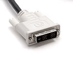
  A male DVI-D (single link) connector | |||
| Type | Digital computer video connector | ||
|---|---|---|---|
| Production history | |||
| Designer | Digital Display Working Group | ||
| Designed | April 1999 | ||
| Produced | 1999–present | ||
| Superseded | VGA connector | ||
| Superseded by | DisplayPort, HDMI | ||
| General specifications | |||
| Hot pluggable | Yes | ||
| External | Yes | ||
| Video signal |
Digital video stream: Single link: 1920 × 1200 (WUXGA) @ 60 Hz Dual link: 2560 × 1600 (WQXGA) @ 60 Hz Analog video stream: 1920 × 1200 (WUXGA) @ 60 Hz | ||
| Pins | 29 | ||
| Data | |||
| Bitrate |
(Single link) 3.96 Gbit/s (Dual link) 7.92 Gbit/s | ||
| Max. devices | 1 | ||
| Protocol | 3 × transition minimized differential signaling data and clock | ||
| Pin out | |||
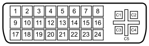 | |||
| A female DVI-I socket from the front | |||
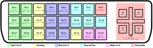 | |||
| Color coded (click to read text) | |||
| Pin 1 | TMDS data 2− | Digital red− (link 1) | |
| Pin 2 | TMDS data 2+ | Digital red+ (link 1) | |
| Pin 3 | TMDS data 2/4 shield | ||
| Pin 4 | TMDS data 4− | Digital green− (link 2) | |
| Pin 5 | TMDS data 4+ | Digital green+ (link 2) | |
| Pin 6 | DDC clock | ||
| Pin 7 | DDC data | ||
| Pin 8 | Analog vertical sync | ||
| Pin 9 | TMDS data 1− | Digital green− (link 1) | |
| Pin 10 | TMDS data 1+ | Digital green+ (link 1) | |
| Pin 11 | TMDS data 1/3 shield | ||
| Pin 12 | TMDS data 3− | Digital blue− (link 2) | |
| Pin 13 | TMDS data 3+ | Digital blue+ (link 2) | |
| Pin 14 | +5 V | Power for monitor when in standby | |
| Pin 15 | Ground | Return for pin 14 and analog sync | |
| Pin 16 | Hot plug detect | ||
| Pin 17 | TMDS data 0− | Digital blue− (link 1) and digital sync | |
| Pin 18 | TMDS data 0+ | Digital blue+ (link 1) and digital sync | |
| Pin 19 | TMDS data 0/5 shield | ||
| Pin 20 | TMDS data 5− | Digital red− (link 2) | |
| Pin 21 | TMDS data 5+ | Digital red+ (link 2) | |
| Pin 22 | TMDS clock shield | ||
| Pin 23 | TMDS clock+ | Digital clock+ (links 1 and 2) | |
| Pin 24 | TMDS clock− | Digital clock− (links 1 and 2) | |
| C1 | Analog red | ||
| C2 | Analog green | ||
| C3 | Analog blue | ||
| C4 | Analog horizontal sync | ||
| C5 | Analog ground | Return for R, G, and B signals | |
Digital Visual Interface (DVI) is a video display interface developed by the Digital Display Working Group (DDWG). The digital interface is used to connect a video source, such as a video display controller, to a display device, such as a computer monitor. It was developed with the intention of creating an industry standard for the transfer of digital video content.
This interface is designed to transmit uncompressed digital video and can be configured to support multiple modes such as DVI-A (analog only), DVI-D (digital only) or DVI-I (digital and analog). Featuring support for analog connections, the DVI specification is compatible with the VGA interface.[1] This compatibility, along with other advantages, led to its widespread acceptance over competing digital display standards Plug and Display (P&D) and Digital Flat Panel (DFP).[2] Although DVI is predominantly associated with computers, it is sometimes used in other consumer electronics such as television sets and DVD players.
DVI's digital video transmission format is based on panelLink, a serial format developed by Silicon Image that utilizes a high-speed serial link called transition minimized differential signaling (TMDS). Like modern analog VGA connectors, the DVI connector includes pins for the display data channel (DDC). A newer version of DDC called DDC2 allows the graphics adapter to read the monitor's extended display identification data (EDID). If a display supports both analog and digital signals in one DVI-I input, each input method can host a distinct EDID. Since the DDC can only support one EDID, this can be a problem if both the digital and analog inputs in the DVI-I port detect activity. It is up to the display to choose which EDID to send.
When a source and display are connected, the source first queries the display's capabilities by reading the monitor EDID block over an I²C link. The EDID block contains the display's identification, color characteristics (such as gamma value), and table of supported video modes. The table can designate a preferred mode or native resolution. Each mode is a set of CRT timing values that define the duration and frequency of the horizontal/vertical sync, the positioning of the active display area, the horizontal resolution, vertical resolution, and refresh rate.
For backward compatibility with displays using analog VGA signals, some of the contacts in the DVI connector carry the analog VGA signals. To ensure a basic level of interoperability, DVI compliant devices are required to support one baseline video mode, "low pixel format" (640 × 480 at 60 Hz). Digitally encoded video pixel data is transported using multiple TMDS links. At the electrical level, these links are highly resistant to electrical noise and other forms of analog distortion.
A single link DVI connection consists of four TMDS links; each link transmits data from the source to the device over one twisted pair. Three of the links represent the RGB components (red, green, and blue) of the video signal for a total of 24 bits per pixel. The fourth link carries the pixel clock. The binary data is encoded using 8b10b encoding. DVI does not use packetization, but rather transmits the pixel data as if it were a rasterized analog video signal. As such, the complete frame is drawn during each vertical refresh period. The full active area of each frame is always transmitted without compression. Video modes typically use horizontal and vertical refresh timings that are compatible with CRT displays, though this is not a requirement. In single-link mode, the maximum pixel clock frequency is 165 MHz that supports a maximum resolution of 2.75 megapixels (including blanking interval) at 60 Hz refresh. For practical purposes, this allows a maximum 16:10 screen resolution of 1920 × 1200 at 60 Hz.
To support higher-resolution display devices, the DVI specification contains a provision for dual link. Dual-link DVI doubles the number of TMDS pairs, effectively doubling the video bandwidth. As a result, higher resolutions up to 2560 × 1600 are supported at 60 Hz.
The maximum length recommended for DVI cables is not included in the specification, since it is dependent on the pixel clock frequency. In general, cable lengths up to 4.5 metres (15 ft) will work for display resolutions up to 1920 × 1200. Longer cables up to 15 metres (49 ft) in length can be used with display resolutions 1280 × 1024 or lower. For greater distances, the use of a DVI booster—a signal repeater which may use an external power supply—is recommended to help mitigate signal degradation.


The DVI connector on a device is given one of three names, depending on which signals it implements:
Most DVI connector types—the exception is DVI-A—have pins that pass digital video signals. These come in two varieties: single link and dual link. Single link DVI employs a single 165 MHz transmitter that supports resolutions up to 1920 × 1200 at 60 Hz. Dual link DVI adds six pins, at the center of the connector, for a second transmitter increasing the bandwidth and supporting resolutions up to 2560 × 1600 at 60 Hz.[3] A connector with these additional pins is sometimes referred to as DVI-DL (dual link). Dual link should not be confused with dual display (also known as dual head), which is a configuration consisting of a single computer connected to two monitors, sometimes using a DMS-59 connector for two single link DVI connections.
In addition to digital, some DVI connectors also have pins that pass an analog signal, which can be used to connect an analog monitor. The analog pins are the four that surround the flat blade on a DVI-I or DVI-A connector. A VGA monitor, for example, can be connected to a video source with DVI-I through the use of a passive adapter. Since the analog pins are directly compatible with VGA signaling, passive adapters are simple and cheap to produce, providing a cost-effective solution to support VGA on DVI. The long flat pin on a DVI-I connector is wider than the same pin on a DVI-D connector, so even if the four analog pins were manually removed, it still wouldn't be possible to connect a male DVI-I to a female DVI-D. It is possible, however, to join a male DVI-D connector with a female DVI-I connector.[4]
DVI is the only widespread video standard that includes analog and digital transmission in the same connector.[5] Competing standards are exclusively digital: these include a system using low-voltage differential signaling (LVDS), known by its proprietary names FPD-Link (flat-panel display) and FLATLINK; and its successors, the LVDS Display Interface (LDI) and OpenLDI.
Some DVD players, HDTV sets, and video projectors have DVI connectors that transmit an encrypted signal for copy protection using the High-bandwidth Digital Content Protection (HDCP) protocol. Computers can be connected to HDTV sets over DVI, but the graphics card must support HDCP to play content protected by digital rights management (DRM).

Generalized Timing Formula (GTF) is a VESA standard which can easily be calculated with the Linux gtf utility. Coordinated Video Timings-Reduced Blanking (CVT-RB) is a VESA standard which offers reduced horizontal and vertical blanking for non-CRT based displays.[6]
One of the purposes of DVI stream encoding is to provide a DC-balanced output link that reduces decoding errors. This goal is achieved by using 10-bit symbols for 8-bit or less characters and using the extra bits for the DC balancing.
Like other ways of transmitting video, there are two different regions: the active region, where pixel data is sent, and the control region, where synchronization signals are sent. The active region is encoded using transition-minimized differential signaling, where the control region is encoded with a fixed 8b/10b encoding. As the two schemes yield different 10-bit symbols, a receiver can fully differentiate between active and control regions.
When DVI was designed, most computer monitors were still of the cathode ray tube type that require analog video synchronization signals. The timing of the digital synchronization signals matches the equivalent analog ones, making the process of transforming DVI to and from an analog signal a process that does not require extra (high-speed) memory, expensive at the time.
HDCP is an extra layer that transforms the 10-bit symbols before sending through the link. Only after correct authorization can the receiver undo the HDCP encryption. Control regions are not encrypted in order to let the receiver know when the active region starts.
The DVI data channel operates at a bit-rate that is 10 times the frequency of the clock signal. In other words, in each DVI clock period there is a 10-bit symbol per channel. The set of three 10-bit symbols represents one complete pixel in single link mode and can represent either one or two complete pixels as a set of six 10-bit symbols in dual link mode.
DVI links provide differential pairs for data and for the clock. The specification document allows the data and the clock to not be aligned. However, as the ratio between clock and bit rate is fixed at 1:10, the unknown alignment is kept over time. The receiver must recover the bits on the stream using any of the techniques of clock/data recovery and find then the correct symbol boundary. The DVI specification allows the input clock to vary between 25 MHz and 165 MHz. This 1:6.6 ratio can make pixel recovery difficult, as phase-locked loops, if used, need to work over a large frequency range. One benefit of DVI over other links is that it is relatively straightforward to transform the signal from the digital domain into the analog domain using a video DAC, as both clock and synchronization signals are sent over the link. Fixed frequency links, like DisplayPort, need to reconstruct the clock from the data sent over the link.
The DVI specification includes signaling for reducing power consumption. Similar to the analog VESA display power management signaling (DPMS) standard, a connected device can turn a monitor off when the connected device is powered down, or programmatically if the display controller of the device supports it. Devices with this capability can also attain Energy Star certification.
The analog section of the DVI specification document is brief and points to other specifications like VESA VSIS[7] for electrical characteristics and GTFS for timing information. The idea of the analog link is to keep compatibility with the previous VGA cables and connectors. HSync, Vsync and three video channels are available in both VGA and DVI connectors and are electrically compatible. Auxiliary links like DDC are also available. A passive adapter can be used in order to carry the analog signals between the two connectors.
HDMI is a newer digital audio/video interface developed and promoted by the consumer electronics industry. DVI and HDMI have the same electrical specifications for their TMDS and VESA/DDC links. However HDMI and DVI differ in several key ways.
To promote interoperability between DVI-D and HDMI devices, HDMI source components and displays support DVI-D signalling. For example, an HDMI display can be driven by a DVI-D source because HDMI and DVI-D both define an overlapping minimum set of supported resolutions and frame buffer formats.
Some DVI-D sources use non-standard extensions to output HDMI signals including audio (e.g. ATI 3000-series and NVIDIA GTX 200-series).[8] Some multimedia displays use a DVI to HDMI adapter to input the HDMI signal with audio. Exact capabilities vary by video card specifications.
In the reverse scenario, a DVI display that lacks optional support for HDCP might be unable to display protected content even though it is otherwise compatible with the HDMI source. Features specific to HDMI such as remote control, audio transport, xvYCC and deep color are not usable in devices that support only DVI signals. HDCP compatibility between source and destination devices is subject to manufacturer specifications for each device.
In December 2010, Intel, AMD, and several computer and display manufacturers announced they would stop supporting DVI-I, VGA and LVDS-technologies from 2013/2015, and instead speed up adoption of DisplayPort and HDMI.[9][10] They also stated: "Legacy interfaces such as VGA, DVI and LVDS have not kept pace, and newer standards such as DisplayPort and HDMI clearly provide the best connectivity options moving forward. In our opinion, DisplayPort 1.2 is the future interface for PC monitors, along with HDMI 1.4a for TV connectivity".
By: Wikipedia.org
Edited: 2021-06-18 19:02:05
Source: Wikipedia.org